

Bucket Elevator for Fertilizer
LANE Bucket Elevator for fertilizer Technical Features & Configuration Selection
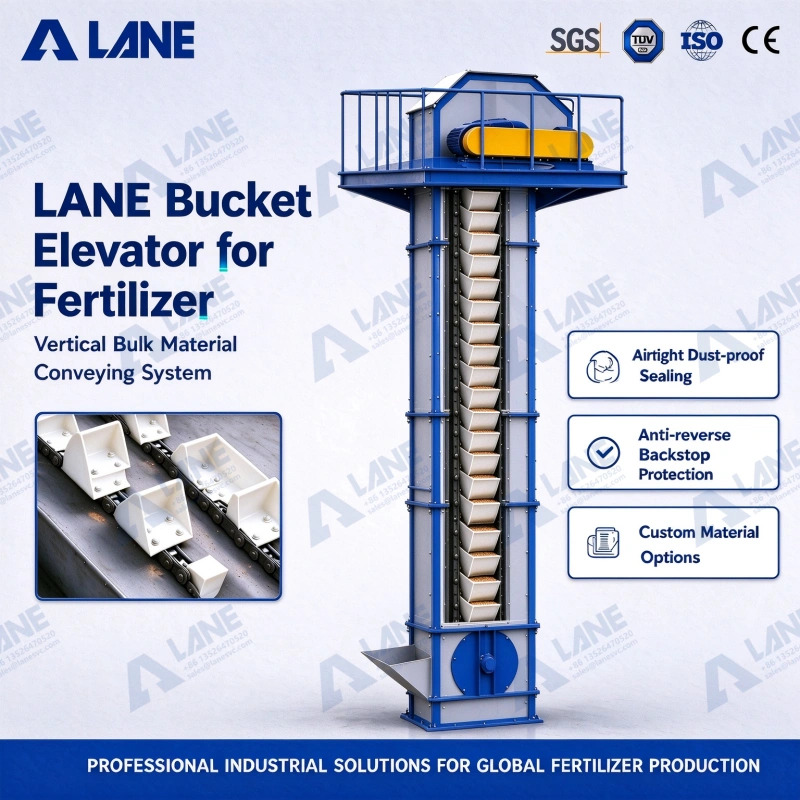
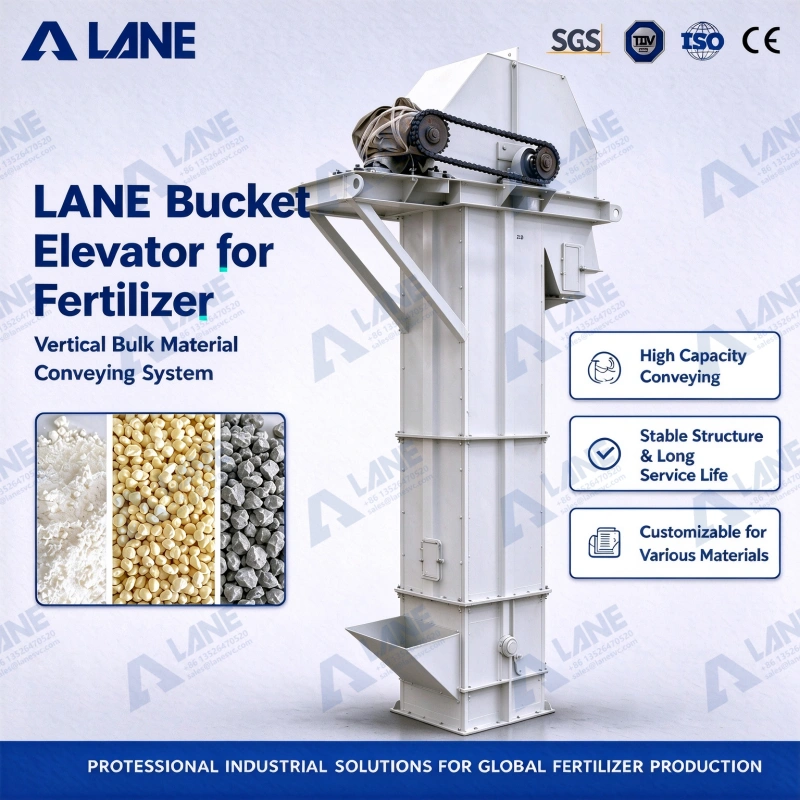
• Heavy plate welded casing: The casing is fabricated from high-strength thick carbon steel plates via laser cutting and stiffener welding processes, guaranteeing structural rigidity and vibration resistance under full-load continuous operation.
• Airtight dust-proof sealing: Anti-corrosion sealing gaskets are fitted at casing flange joints, and special shaft sealing technology is adopted at shaft ends to block dust leakage and isolate external air and moisture.
• Mechanical backstop drive protection: Equipped with a dedicated reducer and motor drive assembly. A mechanical backstop device is built into the transmission system to immediately lock the traction member in case of unexpected power failure, preventing material blockage caused by gravity reverse rotation.
• Multi-material custom options: Targeted material selection based on material properties. SS304/SS316L stainless steel for highly corrosive fertilizers; NM400 wear-resistant steel liners for highly abrasive ores; HDPE (High Density Polyethylene) or nylon buckets for grain conveying.
• Operational safety monitoring components: Optional slip speed sensors, misalignment switches, bearing temperature monitors and anti-block limit switches to provide mechanical and electrical overload protection.
• Modular maintenance structure: Designed with standardized segmented modules. Access doors and sight glasses are installed on the head, casing sections and boot to facilitate fine adjustment of chain/belt tension and routine inspection of wearing parts by operators.
Main Components and Working Principle
Main Components
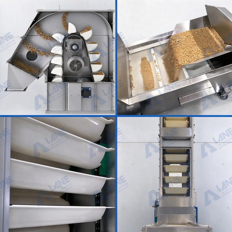
• Buckets: Directly carry materials. Their shape, volume, spacing and material affect loading efficiency, discharge performance and material residue. For different fertilizers, particle size, flowability and wear characteristics need to be considered.
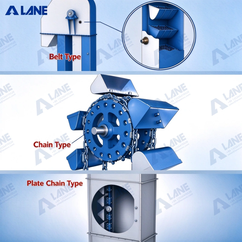
• Traction Members (Belt or Chain): Drive buckets for cyclic operation. Belt-type and chain-type structures have different applicable conditions, and selection shall be based on material characteristics, load, operating environment and maintenance requirements.
• Drive Unit: Usually composed of a motor and corresponding transmission parts to provide power for elevation. Drive configuration needs to match actual conveying load, lifting height and operating requirements.
• Head Section and Discharge: Located at the top of the equipment, responsible for changing bucket travel direction and completing material discharge.
• Casing: Provides an enclosed operating space for upward and return travel of buckets. Proper structural design helps limit dust escape and protects internal moving parts.
• Boot Section and Inlet: Located at the bottom of the equipment, receiving materials and enabling bucket loading. Uneven feeding or material accumulation at the bottom may reduce lifting efficiency and cause blockage in severe cases.
• Take-up and Maintenance Components: Maintain proper tension of traction members and enable inspection, adjustment and maintenance. Specific configuration depends on equipment structure.
Working Principle
The Bucket Elevator for fertilizer lifts materials from the equipment bottom to the top via cyclically moving buckets and delivers materials to designated downstream equipment.
• Feeding and Loading: Fertilizer enters from the bottom inlet, and buckets pick up materials under proper feeding conditions.
• Vertical Lifting: The motor drives the transmission system to move the belt or chain together with buckets upward along the casing.
• Top Discharge: When buckets reach the head section, materials are discharged into silos, mixers or other receiving equipment through discharge methods matching the equipment design.
• Empty Bucket Return: Buckets after discharge travel back to the equipment bottom along the return side for the next cycle.
Technical Parameter Table
| MODEL | SILO VOLUME (m³/h) | MAX. FEED SIZE (mm) | POWER (kW) | SILO WIDTH (mm) | SILO DISTANCE (mm) | LINEAR VELOCITY (m/h) |
|---|---|---|---|---|---|---|
| LAE-160 | 5.4/9.6 | 25 | 3 | 160 | 280 | 1.4 |
| LAE-250 | 12/22 | 35 | 4 | 250 | 360 | 1.6 |
| LAE-315 | 17/30 | 45 | 5.5 | 315 | 410 | 1.6 |
| LAE-400 | 24/40 | 55 | 7.5 | 400 | 480 | 1.8 |
| LAE-500 | 32/50 | 65 | 11 | 500 | 530 | 1.8 |
| LAE-630 | 40/60 | 75 | 15 | 630 | 600 | 2 |
Multi-industry Application Scope
• Agriculture and grain handling: Perfect for high-capacity, gentle elevation of corn, wheat, soybeans, rice, seeds and animal feed pellets to effectively prevent crop breakage.
• Fertilizer and chemical processing: Safely convey NPK compound fertilizer, urea prills, phosphate, potash and various chemical powders to avoid material deterioration and equipment corrosion.
• Cement and building materials: Outstanding wear resistance for continuous elevation of heavy aggregates including clinker, ordinary cement, sand, gravel, limestone, gypsum and crushed stone.
• Mining and metallurgy: Engineered for handling highly abrasive and high-temperature ores such as coal, iron ore, copper concentrate, bauxite and slag.
• Food and pharmaceutical production: Food-grade plastic or stainless steel buckets are adopted to ensure contamination-free conveying of sugar, salt, coffee beans, flour and granular raw materials.
• Biomass: Reliable vertical feeding system for smooth conveying of wood chips, wood pellets, biomass waste and coal dust.
Application of Bucket Elevator for fertilizer in Fertilizer Production Lines
Bucket Elevator for fertilizer are mainly responsible for vertical material conveying between different processes. Proper elevator configuration helps factories optimize space utilization and realize continuous connection between upstream and downstream equipment.
Typical fertilizer production process:
Raw material storage → Bucket Elevator for fertilizer → Batching and mixing → Granulation → Drying and cooling → Screening → Finished product packaging
In actual projects, Bucket Elevator for fertilizer can connect silos, mixers, granulation equipment, drying equipment or screening equipment according to material flow and production line layout. Equipment selection shall consider processing capacity, inlet and outlet height of upstream and downstream equipment as well as material characteristics.
Common Conveying Problems and Solutions
|
Common Problems
|
Key Solutions
|
|---|---|
|
Material adhesion and incomplete discharge
|
Optimize bucket shape, material and discharge structure
|
|
Uneven feeding and bottom material accumulation
|
Adjust feeding mode and inlet layout
|
|
Dust escape
|
Inspect casing connections, access doors and inlet/outlet interfaces
|
|
Belt misalignment or chain wear
|
Check tension, alignment and matching of traction members
|
|
Corrosion and component wear
|
Select materials according to chemical properties and abrasiveness of materials
|
Frequently Asked Questions (FAQ)
1. What are the differences between belt-type and chain-type Bucket Elevator for fertilizer?
Belt-type models are generally suitable for free-flowing, low-abrasion granular materials; chain-type models can be used for heavy-duty or highly abrasive working conditions. Final selection also needs to consider material temperature, equipment structure, operating load and maintenance requirements.
2. What factors determine the conveying capacity of a Bucket Elevator for fertilizer?
It mainly depends on bucket volume, bucket spacing, operating speed, material bulk density and effective filling rate. Material particle size, flowability, feeding and discharge conditions also affect actual conveying capacity.
3. How to reduce dust and material leakage during fertilizer conveying?
Comprehensive consideration of bucket structure, feeding mode, discharge design, casing connections and inlet/outlet interfaces is required. For dust-prone materials, dust removal configuration shall be evaluated according to site requirements; casing sealing alone cannot resolve all issues.
4. How to select a Bucket Elevator for fertilizer according to material characteristics and lifting height?
First confirm material particle size, density, moisture content, abrasiveness and corrosiveness, then carry out type selection combined with target capacity, lifting height, installation space and upstream/downstream equipment layout. Final drive power and equipment specifications shall be calculated and determined based on actual working conditions.